Part 1
요약·해설
공식 PNG 2개, 중첩 예제를 포함한 코드 8개, property type 표 9행과 unit-address·compatible·reg·status·interrupts semantics를 보존했습니다.
Node · path · label
unit · reg
9 type
phandle · alias · chosen
Part 2
접을 수 있는 영어 원문 전체
영어 원문 전체 펼치기
8519482151AA52DAA5329AC0C9B7B052B24DCAA1544E3EA64C56D767D9FED297
.. _dt-syntax:

Syntax and structure
####################

As the name indicates, a devicetree is a tree. The human-readable text format
for this tree is called DTS (for devicetree source), and is defined in the
`Devicetree specification`_.

.. _Devicetree specification: https://www.devicetree.org/

This page's purpose is to introduce devicetree in a more gradual way than the
specification. However, you may still need to refer to the specification to
understand some detailed cases.

.. contents:: Contents
   :local:

Example
*******

Here is an example DTS file:

.. code-block:: devicetree

   /dts-v1/;

   / {
           a-node {
                   subnode_nodelabel: a-sub-node {
                           foo = <3>;
                   };
           };
   };

The ``/dts-v1/;`` line means the file's contents are in version 1 of the DTS
syntax, which has replaced a now-obsolete "version 0".

Nodes
*****

Like any tree data structure, a devicetree has a hierarchy of *nodes*.
The above tree has three nodes:

#. A root node: ``/``
#. A node named ``a-node``, which is a child of the root node
#. A node named ``a-sub-node``, which is a child of ``a-node``

.. _dt-node-labels:

Nodes can be assigned *node labels*, which are unique shorthands that refer to
the labeled node. Above, ``a-sub-node`` has the node label
``subnode_nodelabel``. A node can have zero, one, or multiple node labels. You
can use node labels to refer to the node elsewhere in the devicetree.

Devicetree nodes have *paths* identifying their locations in the tree. Like
Unix file system paths, devicetree paths are strings separated by slashes
(``/``), and the root node's path is a single slash: ``/``. Otherwise, each
node's path is formed by concatenating the node's ancestors' names with the
node's own name, separated by slashes. For example, the full path to
``a-sub-node`` is ``/a-node/a-sub-node``.

Properties
**********

Devicetree nodes can also have *properties*. Properties are name/value pairs.
Property values can be any sequence of bytes. In some cases, the values are an
array of what are called *cells*. A cell is just a 32-bit unsigned integer.

Node ``a-sub-node`` has a property named ``foo``, whose value is a cell with
value 3. The size and type of ``foo``\ 's value are implied by the enclosing
angle brackets (``<`` and ``>``) in the DTS.

See :ref:`dt-writing-property-values` below for more example property values.

Devicetrees reflect hardware
****************************

In practice, devicetree nodes usually correspond to some hardware, and the node
hierarchy reflects the hardware's physical layout. For example, let's consider
a board with three I2C peripherals connected to an I2C bus controller on an SoC,
like this:

.. figure:: ../../../../build/dts/zephyr_dt_i2c_high_level.png
   :alt: representation of a board with three I2C peripherals
   :figclass: align-center

Nodes corresponding to the I2C bus controller and each I2C peripheral would be
present in the devicetree. Reflecting the hardware layout, the
I2C peripheral nodes would be children of the bus controller node.
Similar conventions exist for representing other types of hardware.

The DTS would look something like this:

.. code-block:: devicetree

   /dts-v1/;

   / {
           soc {
                   i2c-bus-controller {
                           i2c-peripheral-1 {
                           };
                           i2c-peripheral-2 {
                           };
                           i2c-peripheral-3 {
                           };
                   };
           };
   };

Properties in practice
**********************

In practice, properties usually describe or configure the hardware the node
represents. For example, an I2C peripheral's node has a property whose value is
the peripheral's address on the bus.

Here's a tree representing the same example, but with real-world node
names and properties you might see when working with I2C devices.

.. figure:: ../../../../build/dts/zephyr_dt_i2c_example.png
   :figclass: align-center

   I2C devicetree example with real-world names and properties.
   Node names are at the top of each node with a gray background.
   Properties are shown as "name=value" lines.

This is the corresponding DTS:

.. code-block:: devicetree

   /dts-v1/;

   / {
           soc {
                   i2c@40003000 {
                           compatible = "nordic,nrf-twim";
                           reg = <0x40003000 0x1000>;

                           apds9960@39 {
                                   compatible = "avago,apds9960";
                                   reg = <0x39>;
                           };
                           ti_hdc@43 {
                                   compatible = "ti,hdc", "ti,hdc1010";
                                   reg = <0x43>;
                           };
                           mma8652fc@1d {
                                   compatible = "nxp,fxos8700", "nxp,mma8652fc";
                                   reg = <0x1d>;
                           };
                   };
           };
   };

.. _dt-unit-address:

Unit addresses
**************

In addition to showing more real-world names and properties, the above example
introduces a new devicetree concept: unit addresses. Unit addresses are the
parts of node names after an "at" sign (``@``), like ``40003000`` in
``i2c@40003000``, or ``39`` in ``apds9960@39``. Unit addresses are optional:
the ``soc`` node does not have one.

In devicetree, unit addresses give a node's address in the
address space of its parent node. Here are some example unit addresses for
different types of hardware.

Memory-mapped peripherals
    The peripheral's register map base address.
    For example, the node named ``i2c@40003000`` represents an I2C controller
    whose register map base address is 0x40003000.

I2C peripherals
    The peripheral's address on the I2C bus.
    For example, the child node ``apds9960@39`` of the I2C controller
    in the previous section has I2C address 0x39.

SPI peripherals
    An index representing the peripheral's chip select line number.
    (If there is no chip select line, 0 is used.)

Memory
    The physical start address.
    For example, a node named ``memory@2000000`` represents RAM starting at
    physical address 0x2000000.

Memory-mapped flash
    Like RAM, the physical start address.
    For example, a node named ``flash@8000000`` represents a flash device
    whose physical start address is 0x8000000.

Fixed flash partitions
    This applies when the devicetree is used to store a flash partition table.
    The unit address is the partition's start offset within the flash memory.
    For example, take this flash device and its partitions:

    .. code-block:: devicetree

        flash@8000000 {
            /* ... */
            partitions {
                    partition@0 { /* ... */ };
                    partition@20000 {  /* ... */ };
                    /* ... */
            };
        };

    The node named ``partition@0`` has offset 0 from the start of its flash
    device, so its base address is 0x8000000. Similarly, the base address of
    the node named ``partition@20000`` is 0x8020000.

.. _dt-important-props:

Important properties
********************

.. Documentation maintainers: If you add a property to this list,
   make sure it gets linked to from gen_devicetree_rest.py too.

The devicetree specification defines several standard properties.
Some of the most important ones are:

compatible
    The name of the hardware device the node represents.

    The recommended format is ``"vendor,device"``, like ``"avago,apds9960"``,
    or a sequence of these, like ``"ti,hdc", "ti,hdc1010"``. The ``vendor``
    part is an abbreviated name of the vendor. The file
    :zephyr_file:`dts/bindings/vendor-prefixes.txt` contains a list of commonly
    accepted ``vendor`` names. The ``device`` part is usually taken from the
    datasheet.

    It is also sometimes a value like ``gpio-keys``, ``mmio-sram``, or
    ``fixed-clock`` when the hardware's behavior is generic.

    The build system uses the compatible property to find the right
    :ref:`bindings <dt-bindings>` for the node. Device drivers use
    ``devicetree.h`` to find nodes with relevant compatibles, in order to
    determine the available hardware to manage.

    The ``compatible`` property can have multiple values. Additional values are
    useful when the device is a specific instance of a more general family, to
    allow the system to match from most- to least-specific device drivers.

    Within Zephyr's bindings syntax, this property has type ``string-array``.

reg
    Information used to address the device. The value is specific to the device
    (i.e. is different depending on the compatible property).

    The ``reg`` property is a sequence of ``(address, length)`` pairs. Each
    pair is called a "register block". Values are conventionally written
    in hex.

    Here are some common patterns:

    - Devices accessed via memory-mapped I/O registers (like ``i2c@40003000``):
      ``address`` is usually the base address of the I/O register space, and
      ``length`` is the number of bytes occupied by the registers.
    - I2C devices (like ``apds9960@39`` and its siblings):
      ``address`` is a slave address on the I2C bus. There is no ``length``
      value.
    - SPI devices: ``address`` is a chip select line number; there is no
      ``length``.

    You may notice some similarities between the ``reg`` property and common
    unit addresses described above. This is not a coincidence. The ``reg``
    property can be seen as a more detailed view of the addressable resources
    within a device than its unit address.

status
    A string which describes whether the node is enabled.

    The devicetree specification allows this property to have values
    ``"okay"``, ``"disabled"``, ``"reserved"``, ``"fail"``, and ``"fail-sss"``.
    Only the values ``"okay"`` and ``"disabled"`` are currently relevant to
    Zephyr; use of other values currently results in undefined behavior.

    A node is considered enabled if its status property is either ``"okay"`` or
    not defined (i.e. does not exist in the devicetree source). Nodes with
    status ``"disabled"`` are explicitly disabled. (For backwards
    compatibility, the value ``"ok"`` is treated the same as ``"okay"``, but
    this usage is deprecated.) Devicetree nodes which correspond to physical
    devices must be enabled for the corresponding ``struct device`` in the
    Zephyr driver model to be allocated and initialized.

interrupts
    Information about interrupts generated by the device, encoded as an array
    of one or more *interrupt specifiers*. Each interrupt specifier has some
    number of cells. See section 2.4, *Interrupts and Interrupt Mapping*, in the
    `Devicetree Specification release v0.3`_ for more details.

    Zephyr's devicetree bindings language lets you give a name to each cell in
    an interrupt specifier.

.. _Devicetree Specification release v0.3:
   https://www.devicetree.org/specifications/

.. highlight:: none

.. note::

   Earlier versions of Zephyr made frequent use of the ``label`` property,
   which is distinct from the standard :ref:`node label <dt-node-labels>`.
   Use of the label *property* in new devicetree bindings, as well as use of
   the :c:macro:`DT_LABEL` macro in new code, are actively discouraged. Label
   properties continue to persist for historical reasons in some existing
   bindings and overlays, but should not be used in new bindings or device
   implementations.

.. _dt-writing-property-values:

Writing property values
***********************

This section describes how to write property values in DTS format. The property
types in the table below are described in detail in :ref:`dt-bindings`.

Some specifics are skipped in the interest of keeping things simple; if you're
curious about details, see the devicetree specification.

.. list-table::
   :header-rows: 1
   :widths: 1 4 4

   * - Property type
     - How to write
     - Example

   * - string
     - Double quoted
     - ``a-string = "hello, world!";``

   * - int
     - between angle brackets (``<`` and ``>``)
     - ``an-int = <1>;``

   * - boolean
     - for ``true``, with no value (for ``false``, use ``/delete-property/``)
     - ``my-true-boolean;``

   * - array
     - between angle brackets (``<`` and ``>``), separated by spaces
     - ``foo = <0xdeadbeef 1234 0>;``

   * - uint8-array
     - in hexadecimal *without* leading ``0x``, between square brackets (``[`` and ``]``).
     - ``a-byte-array = [00 01 ab];``

   * - string-array
     - separated by commas
     - ``a-string-array = "string one", "string two", "string three";``

   * - phandle
     - between angle brackets (``<`` and ``>``)
     - ``a-phandle = <&mynode>;``

   * - phandles
     - between angle brackets (``<`` and ``>``), separated by spaces
     - ``some-phandles = <&mynode0 &mynode1 &mynode2>;``

   * - phandle-array
     - between angle brackets (``<`` and ``>``), separated by spaces
     - ``a-phandle-array = <&mynode0 1 2>, <&mynode1 3 4>;``

Additional notes on the above:

- The values in the ``phandle``, ``phandles``, and ``phandle-array`` types are
  described further in :ref:`dt-phandles`

- Boolean properties are true if present. They should not have a value.
  A boolean property is only false if it is completely missing in the DTS.

- The ``foo`` property value above has three *cells* with values 0xdeadbeef, 1234,
  and 0, in that order. Note that hexadecimal and decimal numbers are allowed and
  can be intermixed. Since Zephyr transforms DTS to C sources, it is not
  necessary to specify the endianness of an individual cell here.

- 64-bit integers are written as two 32-bit cells in big-endian order. The value
  0xaaaa0000bbbb1111 would be written ``<0xaaaa0000 0xbbbb1111>``.

- The ``a-byte-array`` property value is the three bytes 0x00, 0x01, and 0xab, in
  that order.

- Parentheses, arithmetic operators, and bitwise operators are allowed. The
  ``bar`` property contains a single cell with value 64:

  .. code-block:: devicetree

     bar = <(2 * (1 << 5))>;

  Note that the entire expression must be parenthesized.

- Property values refer to other nodes in the devicetree by their *phandles*.
  You can write a phandle using ``&foo``, where ``foo`` is a :ref:`node label
  <dt-node-labels>`. Here is an example devicetree fragment:

  .. code-block:: devicetree

     foo: device@0 { };
     device@1 {
             sibling = <&foo 1 2>;
     };

  The ``sibling`` property of node ``device@1`` contains three cells, in this order:

  #. The ``device@0`` node's phandle, which is written here as ``&foo`` since
     the ``device@0`` node has a node label ``foo``
  #. The value 1
  #. The value 2

  In the devicetree, a phandle value is a cell -- which again is just a 32-bit
  unsigned int. However, the Zephyr devicetree API generally exposes these
  values as *node identifiers*. Node identifiers are covered in more detail in
  :ref:`dt-from-c`.

- Array and similar type property values can be split into several ``<>``
  blocks, like this:

  .. code-block:: devicetree

     foo = <1 2>, <3 4>;                         // Okay for 'type: array'
     foo = <&label1 &label2>, <&label3 &label4>; // Okay for 'type: phandles'
     foo = <&label1 1 2>, <&label2 3 4>;         // Okay for 'type: phandle-array'

  This is recommended for readability when possible if the value can be
  logically grouped into blocks of sub-values.

.. _dt-alias-chosen:

Aliases and chosen nodes
************************

There are two additional ways beyond :ref:`node labels <dt-node-labels>` to
refer to a particular node without specifying its entire path: by alias, or by
chosen node.

Here is an example devicetree which uses both:

.. code-block:: devicetree

   /dts-v1/;

   / {
   	chosen {
   		zephyr,console = &uart0;
        };

   	aliases {
   		my-uart = &uart0;
   	};

   	soc {
   		uart0: serial@12340000 {
   			...
   		};
   	};
   };

The ``/aliases`` and ``/chosen`` nodes do not refer to an actual hardware
device. Their purpose is to specify other nodes in the devicetree.

Above, ``my-uart`` is an alias for the node with path ``/soc/serial@12340000``.
Using its node label ``uart0``, the same node is set as the value of the chosen
``zephyr,console`` node.

Zephyr sample applications sometimes use aliases to allow overriding the
particular hardware device used by the application in a generic way. For
example, :zephyr:code-sample:`blinky` uses this to abstract the LED to blink via the
``led0`` alias.

The ``/chosen`` node's properties are used to configure system- or
subsystem-wide values. See :ref:`devicetree-chosen-nodes` for more information.
Part 3
한국어 전문 번역
DTS 문법과 구조
Devicetree는 이름 그대로 tree이며 사람이 읽는 text 형식을 Devicetree Source, 즉 DTS라고 합니다. 세부 corner case는 Devicetree Specification을 참조해야 하지만 이 문서는 핵심을 단계적으로 소개합니다.
기본 예제
/dts-v1/;

/ {
        a-node {
                subnode_nodelabel: a-sub-node {
                        foo = <3>;
                };
        };
};/dts-v1/;은 현재 파일이 obsolete version 0을 대체한 DTS syntax version 1을 사용한다는 뜻입니다.
Node
예제 tree는 root /, root child a-node, 그 child a-sub-node 세 node로 구성됩니다.
Node label은 node를 가리키는 고유한 짧은 이름입니다. a-sub-node에는 subnode_nodelabel이 붙었습니다. 한 node는 label이 없거나 하나 또는 여러 개일 수 있으며 tree의 다른 위치에서 이 label로 참조합니다.
Node path는 Unix filesystem처럼 slash로 계층을 구분합니다. Root path는 /이고 각 ancestor 이름과 자신의 이름을 이어 붙입니다. 따라서 a-sub-node의 전체 path는 /a-node/a-sub-node입니다.
Property
Property는 node의 name/value pair입니다. 값은 임의의 byte sequence가 될 수 있고 일부는 cell 배열입니다. Cell은 32-bit unsigned integer입니다. 예제의 foo는 angle bracket이 크기와 형식을 나타내며 값 3인 cell 하나를 가집니다.
Tree는 실제 hardware 배치를 반영
실제 node는 보통 hardware에 대응하고 계층은 물리 연결을 반영합니다. SoC의 I2C controller에 peripheral 세 개가 연결된 board를 보겠습니다.
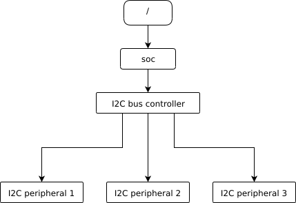
I2C controller와 peripheral마다 node가 있고, 물리 연결과 마찬가지로 peripheral node는 controller node의 child가 됩니다.
/dts-v1/;

/ {
        soc {
                i2c-bus-controller {
                        i2c-peripheral-1 {
                        };
                        i2c-peripheral-2 {
                        };
                        i2c-peripheral-3 {
                        };
                };
        };
};
실제 property 사용
Property는 node가 나타내는 hardware를 설명하거나 설정합니다. I2C peripheral node의 reg는 bus address를 나타냅니다.
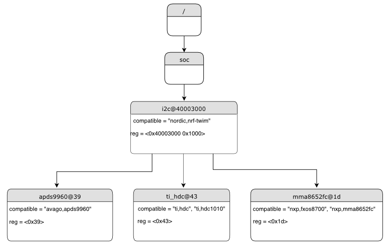
/dts-v1/;

/ {
        soc {
                i2c@40003000 {
                        compatible = "nordic,nrf-twim";
                        reg = <0x40003000 0x1000>;

                        apds9960@39 {
                                compatible = "avago,apds9960";
                                reg = <0x39>;
                        };
                        ti_hdc@43 {
                                compatible = "ti,hdc", "ti,hdc1010";
                                reg = <0x43>;
                        };
                        mma8652fc@1d {
                                compatible = "nxp,fxos8700", "nxp,mma8652fc";
                                reg = <0x1d>;
                        };
                };
        };
};
Unit address
Unit address는 node 이름의 @ 뒤 부분입니다. i2c@40003000의 40003000, apds9960@39의 39가 예입니다. 선택 사항이므로 soc처럼 없는 node도 있습니다. 값은 parent node의 address space에서 이 node가 차지하는 주소를 뜻합니다.
- Memory-mapped peripheral: register map base.
i2c@40003000은 base 0x40003000 - I2C peripheral: I2C bus address.
apds9960@39는 0x39 - SPI peripheral: chip-select line index. Chip select가 없으면 0
- Memory: physical start address.
memory@2000000은 0x2000000 - Memory-mapped flash: RAM과 같은 physical start address.
flash@8000000은 0x8000000 - Fixed flash partition: flash 시작점에서 partition start offset
Fixed partition의 unit address 예제입니다.
 flash@8000000 {
     /* ... */
     partitions {
             partition@0 { /* ... */ };
             partition@20000 {  /* ... */ };
             /* ... */
     };
};partition@0은 flash 시작에서 offset 0이므로 base 0x8000000이고 partition@20000은 base 0x8020000입니다.
중요한 표준 property
compatible
Node가 나타내는 hardware 장치 이름입니다. 권장 형식은 "vendor,device"이고 더 구체적인 장치부터 일반 family까지 여러 문자열을 둘 수 있습니다. Vendor 약어는 dts/bindings/vendor-prefixes.txt의 공통 목록을 따르고 device는 보통 datasheet 이름입니다. gpio-keys, mmio-sram, fixed-clock처럼 generic behavior는 vendor 없이 사용합니다.
Build system은 compatible로 node binding을 찾고 driver는 public API로 자신이 처리할 compatible의 node를 찾습니다. 여러 값은 가장 구체적인 driver에서 덜 구체적인 driver로 fallback할 수 있게 합니다. Zephyr binding type은 string-array입니다.
reg
장치 address 정보이며 compatible에 따라 의미가 달라집니다. 값은 (address, length) register block의 sequence이고 관례상 16진수로 씁니다. MMIO device는 register base와 byte length, I2C device는 slave address만, SPI device는 chip-select line만 가집니다. Unit address는 reg가 설명하는 addressable resource의 축약된 관점입니다.
status
Node enable 상태 문자열입니다. Specification은 okay, disabled, reserved, fail, fail-sss를 허용하지만 Zephyr에서는 okay와 disabled만 의미가 정의됩니다. Status가 없거나 okay이면 enabled, disabled면 명시적으로 꺼집니다. ok도 호환성을 위해 okay로 처리하지만 deprecated입니다. Physical device node가 enabled여야 대응하는 driver model device가 할당·초기화됩니다.
interrupts
장치가 생성하는 interrupt 정보를 하나 이상의 interrupt specifier 배열로 encode합니다. 각 specifier는 여러 cell을 가질 수 있고 Zephyr binding에서 cell마다 이름을 줄 수 있습니다.
DTS property 값 작성
| Property type | 작성법 | 예제 |
|---|---|---|
string | Double quote로 묶음 | a-string = "hello, world!"; |
int | Angle bracket 안에 작성 | an-int = <1>; |
boolean | true면 값 없이 존재, false는 /delete-property/ | my-true-boolean; |
array | Angle bracket 안에서 공백으로 구분 | foo = <0xdeadbeef 1234 0>; |
uint8-array | 0x 없이 16진수 byte를 square bracket 안에 작성 | a-byte-array = [00 01 ab]; |
string-array | 문자열을 comma로 구분 | a-string-array = "string one", "string two", "string three"; |
phandle | Angle bracket 안에 작성 | a-phandle = <&mynode>; |
phandles | Angle bracket 안에서 공백으로 구분 | some-phandles = <&mynode0 &mynode1 &mynode2>; |
phandle-array | Angle bracket block을 comma로 구분 | a-phandle-array = <&mynode0 1 2>, <&mynode1 3 4>; |
- Phandle 관련 type은 별도 phandle 문서에서 더 자세히 설명합니다.
- Boolean은 property가 존재하면 true이고 값을 쓰지 않습니다. DTS에서 완전히 없을 때만 false입니다.
- Array 예제의 세 cell은 0xdeadbeef, 1234, 0 순서입니다. 16진수와 10진수를 섞을 수 있고 DTS가 C source로 변환되므로 개별 cell endian은 지정하지 않습니다.
- 64-bit integer는 big-endian 순서의 32-bit cell 두 개로 씁니다. 0xaaaa0000bbbb1111은
<0xaaaa0000 0xbbbb1111>입니다. - Byte array 예제는 0x00, 0x01, 0xab 세 byte입니다.
Parentheses, arithmetic, bitwise operator를 사용할 수 있으며 전체 expression을 parentheses로 묶어야 합니다.
bar = <(2 * (1 << 5))>;Property는 node label 앞의 &로 다른 node의 phandle을 참조합니다.
foo: device@0 { };
device@1 {
        sibling = <&foo 1 2>;
};device@1의 sibling 값은 device@0의 phandle, 1, 2 세 cell입니다. Tree 안의 phandle은 32-bit cell이지만 Zephyr public API는 보통 node identifier로 노출합니다.
Array와 유사 type은 논리적 sub-value group마다 여러 angle bracket block으로 나눌 수 있으며 가독성을 위해 권장됩니다.
foo = <1 2>, <3 4>;                         // Okay for 'type: array'
foo = <&label1 &label2>, <&label3 &label4>; // Okay for 'type: phandles'
foo = <&label1 1 2>, <&label2 3 4>;         // Okay for 'type: phandle-array'
Alias와 chosen node
전체 path 없이 node를 가리키는 추가 방식은 alias와 chosen입니다.
/dts-v1/;

/ {
	chosen {
		zephyr,console = &uart0;
     };

	aliases {
		my-uart = &uart0;
	};

	soc {
		uart0: serial@12340000 {
			...
		};
	};
};/aliases와 /chosen은 실제 hardware가 아니라 다른 node를 지정합니다. my-uart는 /soc/serial@12340000의 alias이고 같은 node label uart0이 chosen zephyr,console 값입니다.
Sample은 alias로 board마다 사용할 hardware를 generic하게 바꿀 수 있습니다. Blinky의 led0가 대표적입니다. Chosen property는 system 또는 subsystem 전체에서 쓸 값을 선택합니다.
Source
출처
원문 파일의 단락, directive, 표, 코드, symbol, 경로는 영어 원문 영역에 그대로 보존했습니다.